DESIGNED TO OPERATE AND PROTECT IRRIGATION NETWORKS
Designed to operate and protect irrigation networks
100 Series Control Valves offer exceptionally low-pressure losses at high flow rates.

100 Series Control Valves offer exceptionally low-pressure losses at high flow rates.

Outstanding performance -High flow capacity and very low head losses achieved by a flexible diaphragm that provides a wide water passage throughout the valve’s hydrodynamic body.
Extremely Versatile - The valves are available in sizes 3/4"-24", globe and angle shapes, with an extensive selection of materials, and a full range of control functions and various end connections.
Ultimate Durability - Long life and easy inline maintenance accomplished by structural simplicity and the use of high-quality materials that can withstand the harshest conditions.
Series 100 is designed to work under high pressures over 16 bar or when large diameters are needed. Use them for water conduction and in-field applications for field crops, vineyards, orchards, and greenhouses
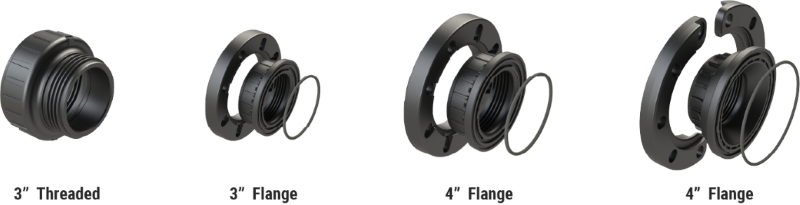
Unique Body design accepts multiple pipe size configurations, allowing for more efficient use of on-hand inventory. Available sizes/connections:

This valve is activated by the line pressure or by an external hydraulic or pneumatic pressure. Valve position is controlled by a 3-way solenoid valve which activates an electric current or electric pulse to open and close the main valve. The standard valve is supplied in the “normally closed” position with a “normally open” position as optional. This hydraulic valve has direct-sealing diaphragm for inline maintenance. No stem, shaft or guide bearings are located within the water passage. Electric activation can be added to other control applications on request.
This valve is activated by the line pressure or by an external hydraulic or pneumatic pressure. Valve position is controlled by a pressure reducing pilot valve to achieve constant outlet (downstream) pressure, regardless of upstream pressure or flow variations. A 3-way pilot valve allows full opening when upstream pressure drops below the pressure set point.


This valve protects the pumping system from water hammer caused by sudden pump shut-off (for example: power failure). Assembled on a T-junction of the main pipeline, this valve instantly opens when the pump stops relieving the returning high pressure wave. The valve slowly closes once the pressure returns to the static level. It can also function as a pressure relief valve. This hydraulic valve has direct-sealing diaphragm for inline maintenance. No stem, shaft or guide bearings are located within the water passage. Line pressure or external hydraulic or pneumatic pressure activates the valve. Two pressure relief pilots – one for opening at a low pressure set point and one for opening at a high pressure set point.
This valve opens instantly when the pressure in the pipeline exceeds the safe level, thus relieving excessive pressure from the network. When the pressure returns to normal, the valve closes slowly at an adjustable pace. The valve is hydraulic with a direct sealing diaphragm for inline maintenance. No stem, shaft or guide bearings are located within the water passage. Line pressure or external hydraulic or pneumatic pressure activates the valve.
D[mm] ≤ √(250 x Flow[m3/hr] / √Pressure [mwc])
Download our FREE Control Valves App with features that help you choose the right valve, at your fingertips.


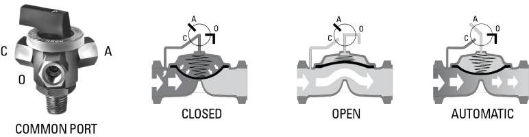
 CLOSED (C): Upstream pressure or pressure from an external source is applied to the control chamber. Initiated by the spring, the diaphragm is pressed down to close the valve drip-tight.
OPEN (O): Relieving the water or air pressure to the atmosphere from the control chamber causes the valve to open.
AUTOMATIC (A): The automatic port of the 3-Way selector is connected to a solenoid, hydraulic relay or pilot which controls the valve. The common port of the 3-Way selector connects the control chamber to either A, O or C, depending on the direction the selector is pointed.


Contact a valve expert to learn which one suits your needs.